< Section 20 | Home | Section 22 >
65% Complete
132. Introduction
https://www.udemy.com/cisco-icnd1/learn/lecture/8657074#overview
133. Router with Separate Interfaces
https://www.udemy.com/cisco-icnd1/learn/lecture/8657078#overview
VLANs and IP subnets in the LAN
- There is typically a one-to-one relationship between an IP subnet and a VLAN in the LAN campus
- For example:
- Engineering hosts are in IP subnet 10.10.10.0/24 and VLAN 10
- Sales hosts are in IP subnet 10.10..20.0/24 and VLAN 20
- Hosts are segragated at Layer 3 by being in different IP subnets and at Layer 2 by being in different VLANs
- Host in different IP subnets need to send traffic via a Router to communicate with each other.
Option 1: Router with different Interfaces
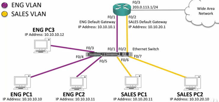
- Router interfaces are configured as default gateways.
- Each interface is associated to its related VLAN
- Hosts in one VLAN can reach hosts in the other VLAN via the Router.
Routers with Separate Interfaces Disadvantages
- You need a separate interface for every VLAN and you are likely to run out of interfaces.
- Traffic being routed with the campus has to go up and down physical Ethernet cables to the router.
Inter-VLAN Routing Lab

Configuration
SW1
conf t
int range f0/1 - 2
switchport mode access
switchport access vlan 10

int f0/3
switchport mode access
switchport access vlan 20

int g0/1
switchport trunk encap dot1q
switchport mode trunk
switchport trunk native vlan 199
SW2
conf t
int range g0/1 - 2
switchport trunk encap dot1q
switchport mode trunk
switchport trunk native vlan 199

int f0/1
switchport mode access
switchport access vlan 10

int f0/2
switchport mode access
switchport access vlan 20
SW3
conf t
int range f0/1 - 2
switchport mode access
switchport access vlan 20

int f0/3
switchport mode access
switchport access vlan 10

int g0/1
switchport trunk encap dot1q
switchport mode trunk
switchport trunk native vlan 199
R1
conf t
int f0/0
ip address 10.10.10.1 255.255.255.0
no shutdown

int f0/1
ip address 10.10.20.1 255.255.255.0
no shutdown
134. Router on a Stick
https://www.udemy.com/cisco-icnd1/learn/lecture/8657082#overview
Know this for the exam!
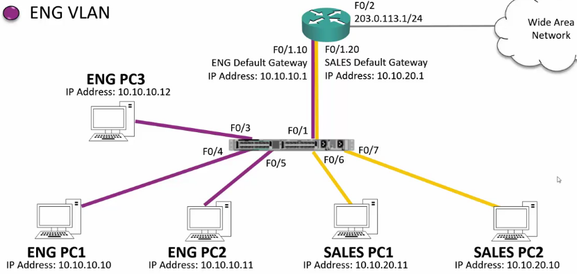
- R1-F0/1
- Configured with no IP address.
- No shutdown
- Create Sub-interface F0/1.10
- Automatically creates a virtual sub-interface
in VLAN 10 - Add IP address 10.10.10.1/24
- Automatically creates a virtual sub-interface
- Create Sub-Interface F0/1.20
- Automatically creates a virtual subinterface
in VLAN 20 - Add IP address 10.10.20.1/24
- Automatically creates a virtual subinterface
R1(config)#interface fastethernet 0/1
R1(config-if)#no ip address
R1(config-if)#no shutdown
R1(config-if)#interface fastethernet 0/1.10
R1(config-subif)#encapsulation dot1q 10
R1(config-subif)#ip address 10.10.10.1 255.255.255.0
R1(config-subif)#interface fastethernet 0/1.20
R1(config-subif)#encapsulation dot1q 20
R1(config-subif)#ip address 10.10.20.1
R1(config-if)#exit
R1(config)ip route 0.0.0.0 0.0.0.0 203.0.113.2
SW1(config)#interface fastethernet 0/1
SW1(config-if)#switchport mode trunk
Router on a Stick Pros and Cons
- Pros
- You DO NOT need a separate physical interface for every VLAN
- This way you are less likely to run out of interfaces
- Cons
- Traffic routed within the campus has to go up an down the same physical Ethernet cable to the Router.
- There is more contention for bandwidth than when using separate interfaces.
Inter-VLAN Routing Lab

My Config:
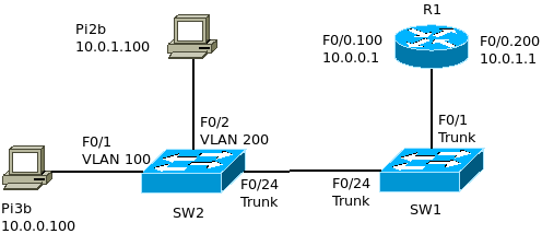
Note: To make this work with my Raspberry Pis, I first had to configure static routes for 10.0.0.0/24
sudo route add -net 10.0.0.0/8 dev etho
SW2
Configure the VLANS
SW2(config)#vlan 100
SW2(config-vlan)#name Sub.0
SW2(config-vlan)#vlan 200
SW2(config-vlan)#name Sub.1
SW2(config-vlan)#vlan 199
SW2(config-vlan)#name Native
Configure the access interfaces F0/1 and F0/2
SW2(config)#interface fastethernet 0/1
SW2(config-if)#switchport mode access
SW2(config-if)#switchport access vlan 100
SW2(config-if)#int f0/2
SW2(config-if)#switch mode access
SW2(config-if)#switch access vlan 200
Configure F0/24 as a trunk
SW2(config)#interface fastethernet 0/24
SW2(config-if)#switchport mode trunk
SW2(config-if)#switchport trunk native vlan 199
SW1
Configure the VLANS
SW1(config)#vlan 100
SW1(config-vlan)#name Sub.0
SW1(config-vlan)#vlan 200
SW1(config-vlan)#name Sub.1
SW1(config-vlan)#vlan 199
SW1(config-vlan)#name Native
Configure Interfaces F0/1 and F0/24 as Trunks
SW1(config)#interface fastethernet 0/1
SW1(config-if)#switchport mode trunk
SW1(config-if)#switchport trunk native vlan 199
SW1(config-if)#int f0/24
SW1(config-if)#switch mode trunk
SW1(config-if)#switch trunk native vlan 199
R1
Configure Interface F0/0 with Sub Interfaces
R1(config)#interface fastethernet 0/0
R1(config-if)#no ip address
R1(config-if)#no shutdown
R1(config-if)#int f0/0.100
R1(config-subif)#encapsulation dot1q 100
R1(config-subif)#ip address 10.0.0.1 255.255.255.0
R1(config-subif)#int f0/0.200
R1(config-subif)#encapsulation dot1q 200
R1(config-subif)#ip address 10.0.1.1 255.255.255.0
135. Layer 3 Switches
https://www.udemy.com/course/cisco-icnd1/learn/lecture/8657096#overview
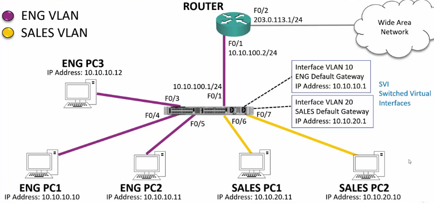
Use the Switch as a Router
- Requires a Layer 3 Switch
- Requires SVI: Switched Virtual Interface
- Configure Virtual Interfaces to correspond to the interfaces you would normally have on a router.
- These also need to correspond to the correct VLAN
Reasons for still using an external Router
- Switches use Ethernet. You might require a different interface for the WAN traffic
- There may be a WAN feature that is required but not supported by the switch.
Configure Inter-VLAN Routing
SW1(config)#ip routing
SW1(config)#interface vlan 10
SW1(config-if)#ip address 10.10.10.1 255.255.255.0
SW1(config-if)#interface vlan 20
SW1(config-if)#ip address 10.10.20.1 255.255.255.0
Configure WAN Routing
This requires another Virtual Interface to connect to the router.
SW1(config)#interface fastethernet 0/1
SW1(config-if)#no switchport
SW1(config-if)#ip address 10.10.100.1 255.255.255.0
SW1(config-if)#exit
SW1(config)#ip route 0.0.0.0 0.0.0.0 10.10.100.2
R1(config)#! Configure Router
R1(config)#interface fastethernet 0/1
R1(config-if)#ip address 10.10.100.2 255.255.255.0
R1(config-if)#no shutdown
R1(config-if)#int f0/2
R1(config-if)#ip address 203.0.113.1 255.255.255.0
R1(config-if)#no shutdown
R1(config-if)#exit
R1(config)#! Configure Routes
R1(config)#ip route 0.0.0.0 0.0.0.0 203.0.113.2
R1(config)#ip route 10.10.0.0 255.255.0.0 10.10.100.1
Pros and Cons for a Layer 3 Switch
- Pros
- Traffic does not need to travel across the campus backplane.
- Traffic does not need to be routed to an external Router
- Cons
- You may still need an external Router for WAN connectivity
136. Layer 3 Switch Lab Demo
https://www.udemy.com/course/cisco-icnd1/learn/lecture/8657104#content
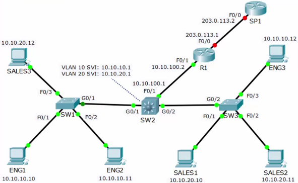
SW2: Configure the virtual interfaces
SW2(config)#ip routing
SW2(config)#interface vlan 10
SW2(config-if)#ip address 10.10.10.1 255.255.255.0
SW2(config-if)#interface vlan 20
SW2(config-if)#ip address 10.10.20.1 255.255.255.0
SW2: Configure F0/1 as a Router Interface with an IP address
SW2(config)#interface fastethernet 0/1
SW2(config-if)#no switchport
SW2(config-if)#ip address 10.10.100.1 255.255.255.0
SW2(config-if)#no shutdown
SW2: Configure the static routes
SW2(config)#ip route 10.10.10.0 255.255.255.0 10.10.10.1
SW2(config)#ip route 10.10.20.0 255.255.255.0 10.10.20.1
SW2(config)#ip route 0.0.0.0 0.0.0.0 10.10.100.2
R1: Configure Interfaces
R1(config)#int f0/1
R1(config-if)#ip address 10.10.100.2 255.255.255.0
R1(config-if)#no shutdown
R1(config-if)#int f0/0
R1(config-if)#ip address 203.0.113.1 255.255.255.0
R1(config-if)#no shutdown
R1: Configure Static Routes
R1(config)#ip route 10.10.0.0 255.255.0.0 10.10.100.1
R1(config)#ip route 0.0.0.0 0.0.0.0 203.0.113.2
You Are Here
137. VLAN and Inter-VLAN Routing Configuration Lab Exercises
https://www.udemy.com/cisco-icnd1/learn/lecture/8657116#overview
23-1 VLAN and Inter-VLAN Routing Configuration Lab Exercise
23-1 VLAN and Inter-VLAN Routing Configuration Answer Key
VTP, Access and Trunk Ports
1) All routers and switches are in a factory default state. View the VLAN
database on SW1 to verify no VLANs have been added.
SW1>sh vlan brief

VLAN Name                             Status    Ports
---- -------------------------------- --------- -------------------------------
1    default                          active    Fa0/1, Fa0/2, Fa0/3, Fa0/4
                                                Fa0/5, Fa0/6, Fa0/7, Fa0/8
                                                Fa0/9, Fa0/10, Fa0/11, Fa0/12
                                                Fa0/13, Fa0/14, Fa0/15, Fa0/16
                                                Fa0/17, Fa0/18, Fa0/19, Fa0/20
                                                Fa0/21, Fa0/22, Fa0/23, Fa0/24
                                                Gig0/1, Gig0/2
1002 fddi-default                     active
1003 token-ring-default               active
1004 fddinet-default                  active
1005 trnet-default                    active
2) View the default switchport status on the link from SW1 to SW2.
SW1#sh int g0/1 switchport
Name: Gig0/1
Switchport: Enabled
Administrative Mode: dynamic auto
Operational Mode: static access
Administrative Trunking Encapsulation: dot1q
Operational Trunking Encapsulation: native
Negotiation of Trunking: On
Access Mode VLAN: 1 (default)
Trunking Native Mode VLAN: 1 (default)
Voice VLAN: none
...
3) Configure the links between switches as trunks.
Repeat all switches
conf t
int range g0/1 - 2
# next command required on SW2 only
switchport trunk encap dot1q
switchport mode trunk
end
4) Add the Eng, Sales and Native VLANs on all switches.
Repeat all switches
conf t
vlan 10
name Eng
vlan 20
name Sales
vlan 199
name Native
end
5) Verify the VLANs are in the database on each switch.
Repeat all switches
show vlan brief
6) Configure the trunk links to use VLAN 199 as the native VLAN for better
security.
Repeat all switches
conf t
int range g0/1 - 2
switchport trunk native vlan 199
end
7) Configure the switchports connected to the PCs with the correct VLAN
configuration.
SW1
conf t
int range f0/1 - 2
switchport mode access
switchport access vlan 10
int f0/3 switchport mode access
switchport access vlan 20
SW3
conf t
int range f0/1 - 2
switchport mode access
switchport access vlan 20
int f0/3
switchport mode access
switchport access vlan 10
end
8) Verify the Eng1 PC has connectivity to Eng3.
10.10.10.10 (Eng1)
C:\>ping 10.10.10.12

Pinging 10.10.10.12 with 32 bytes of data:

Reply from 10.10.10.12: bytes=32 time=1ms TTL=128
Reply from 10.10.10.12: bytes=32 time<1ms TTL=128
Reply from 10.10.10.12: bytes=32 time<1ms TTL=128
Reply from 10.10.10.12: bytes=32 time<1ms TTL=128
9) Verify Sales1 has connectivity to Sales3.
10.10.20.10 (Sales1)
C:\>ping 10.10.20.12

Pinging 10.10.20.12 with 32 bytes of data:

Reply from 10.10.20.12: bytes=32 time<1ms TTL=128
Reply from 10.10.20.12: bytes=32 time<1ms TTL=128
Reply from 10.10.20.12: bytes=32 time<1ms TTL=128
Reply from 10.10.20.12: bytes=32 time<1ms TTL=128
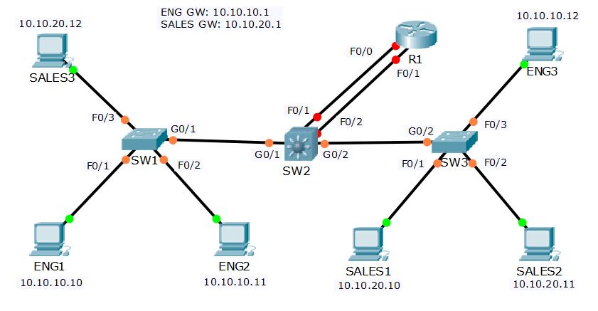
Inter-VLAN Routing – Option 1
Separate Interfaces on Router
10) Configure interface FastEthernet0/0 on R1 as the default gateway for the Eng PCs.
conf t
int f0/0
ip address 10.10.10.1 255.255.255.0
no shutdown
end
11) Configure interface FastEthernet0/1 on R1 as the default gateway for the Sales PCs.
conf t
int f0/1
ip address 10.10.20.1 255.255.255.0
no shutdown
end
12) Configure SW2 to support inter-VLAN routing using R1 as the default gateway.
conf t
int f0/1
switchport mode access
switchport access vlan 10
int f0/2
switchport mode access
switchport access vlan 20
end
13) Verify the Eng1 PC has connectivity to the VLAN 20 interface on R1.
C:\>ping 10.10.20.1

Pinging 10.10.20.1 with 32 bytes of data:

Reply from 10.10.20.1: bytes=32 time=1ms TTL=255
Reply from 10.10.20.1: bytes=32 time<1ms TTL=255
Reply from 10.10.20.1: bytes=32 time<1ms TTL=255
Reply from 10.10.20.1: bytes=32 time<1ms TTL=255
14) Verify the Eng1 PC has connectivity to Sales1.
C:\>ping 10.10.20.10

Pinging 10.10.20.10 with 32 bytes of data:

Request timed out.
Reply from 10.10.20.10: bytes=32 time=1ms TTL=127
Reply from 10.10.20.10: bytes=32 time=9ms TTL=127
Reply from 10.10.20.10: bytes=32 time=1ms TTL=127
15) Clean-up: Shut down interface FastEthernet0/1 on R1.
conf t
int f0/1
shutdown
end
Inter-VLAN Routing – Option 2
Router on a Stick
16) Configure sub-interfaces on FastEthernet0/0 on R1 as the default gateway for the Eng and Sales PCs.
conf t
int f0/1
no ip address 10.10.20.1 255.255.255.0

int f0/0
no ip address 10.10.10.1 255.255.255.0
no shutdown

int f0/0.10
encapsulation dot1q 10
ip address 10.10.10.1 255.255.255.0

int f0/0.20
encapsulation dot1q 20
ip address 10.10.20.1 255.255.255.0

end
17) Configure SW2 to support inter-VLAN routing using R1 as the default gateway.
conf t
int f0/1
switchport trunk encap dot1q
switchport mode trunk
switchport trunk native vlan 199
end
18) Verify the Eng1 PC has connectivity to the VLAN 20 interface on R1.
C:\>ping 10.10.20.1

Pinging 10.10.20.1 with 32 bytes of data:

Reply from 10.10.20.1: bytes=32 time=1ms TTL=255
Reply from 10.10.20.1: bytes=32 time<1ms TTL=255
Reply from 10.10.20.1: bytes=32 time<1ms TTL=255
Reply from 10.10.20.1: bytes=32 time<1ms TTL=255
19) Verify the Eng1 PC has connectivity to Sales1.
C:\>ping 10.10.20.10

Pinging 10.10.20.10 with 32 bytes of data:

Request timed out.
Reply from 10.10.20.10: bytes=32 time<1ms TTL=127
Reply from 10.10.20.10: bytes=32 time<1ms TTL=127
Reply from 10.10.20.10: bytes=32 time<1ms TTL=127
20) Clean-up: Shut down interface FastEthernet0/0 on R1.
conf t
int f0/0
shutdown
end
Inter-VLAN Routing – Option 3
Layer 3 Switch
21) Enable layer 3 routing on SW2.
conf t
ip routing
end
22) Configure SVIs on SW2 to support inter-VLAN routing between the Eng and Sales VLANs.
conf t
int vlan 10
ip address 10.10.10.1 255.255.255.0
int vlan 20
ip address 10.10.20.1 255.255.255.0


23) Verify the Eng1 PC has connectivity to the VLAN 20 interface on SW2.
C:\>ping 10.10.20.1

Pinging 10.10.20.1 with 32 bytes of data:

Reply from 10.10.20.1: bytes=32 time=7ms TTL=255
Reply from 10.10.20.1: bytes=32 time<1ms TTL=255
Reply from 10.10.20.1: bytes=32 time<1ms TTL=255
Reply from 10.10.20.1: bytes=32 time<1ms TTL=255
24) Verify the Eng1 PC has connectivity to Sales1.
C:\>ping 10.10.20.10

Pinging 10.10.20.10 with 32 bytes of data:

Request timed out.
Reply from 10.10.20.10: bytes=32 time=1ms TTL=127
Reply from 10.10.20.10: bytes=32 time<1ms TTL=127
Reply from 10.10.20.10: bytes=32 time<1ms TTL=127
🙂