< Section 19 | Home | Section 21 >
61% Complete
124. Introduction
https://www.udemy.com/cisco-icnd1/learn/lecture/8657024#content
125. Campus LAN Design – Core, Distribution and Access Layers
https://www.udemy.com/cisco-icnd1/learn/lecture/8657030#content
Overview
- Multi-building LAN network design (not multi-city WAN)
- Should be designed for scalability, performance and security
- To aid best practice designs, the network topology is split into access, distribution and core layers
- The layers have their own design principles and characteristics.
Access Layer
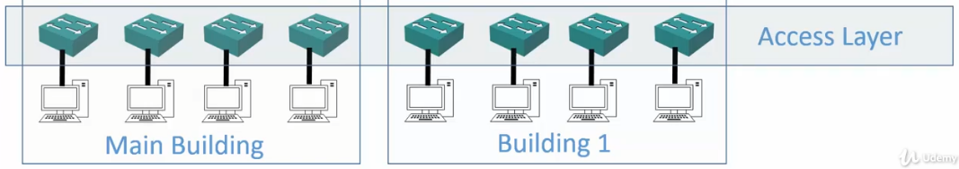
- End hosts, such as desktops, servers and IP phones connect into the network at the access layer
- It is designed to have a high port count at an affordable cost.
- Desktops typically have only one Network Interface Card (NIC) so they connect into one switch or Wireless Access Point.
- Servers will often have dual NICs and connect to a pair of redundant switches
- Client access security measures are enabled at the Access Layer
Distribution Layer
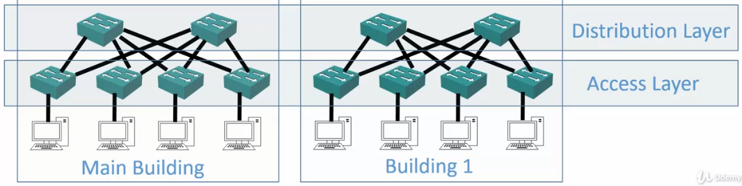
- Access Layer switches uplink to Distribution Layer switches
- The Distribution Layer switches serve as an aggregation point for the Access Layer and provide scalability.
- Distribution Layer switches are typically deployed in redundant pairs, with downstream Access Layer switches connected to both.
- If a switch goes down, the endpoints will not lose connectivity.
- End hosts are not typically connected here.
- Most software policy such as QoS (Quality of Service) is enabled at this layer.
Core Layer
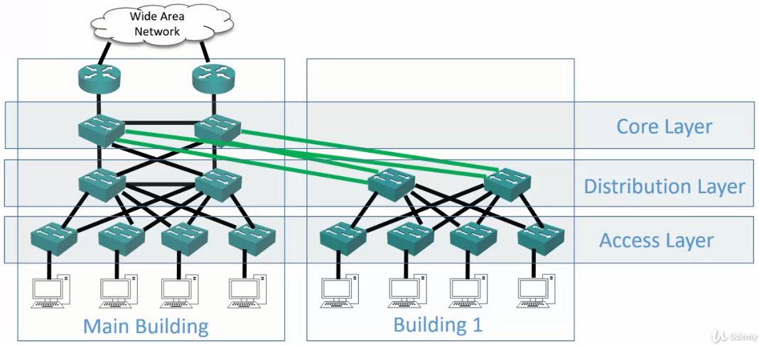
- Notice one pair of Core Layer switches vs. multiple pairs of distribution layer switches per building.
- Distribution Layer switches uplink to Core Layer switches.
- Core Layer switches are typically deployed in redundant pairs, with downstream Distribution Layer switches connected to both.
- Traffic between different parts of the campus travels through the core, so it is designed for speed and resiliency
- Software policies slow the switch down, so these should be avoided in the Core Layer.
Collapsed Distribution and Core
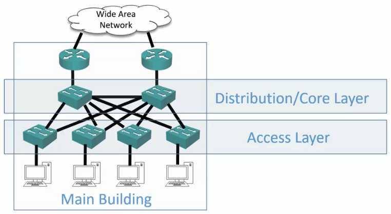
- Smaller campuses do not need the scalability of three separate layers.
- In these cases, a Collapsed Distribution and Core layer is used, where the Distribution and Core layer functions are performed on the same hardware device.
126. Why we have VLANS
https://www.udemy.com/cisco-icnd1/learn/lecture/8657038#content
Router Operations
- Routers operate at Layer 3 of the OSI stack.
- Hosts in separate IP subnets must send traffic via a route to communicate.
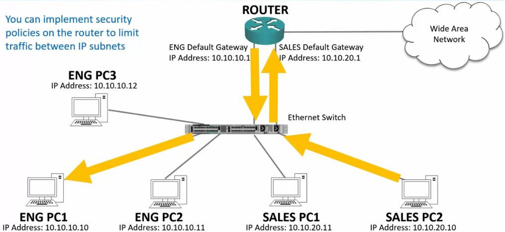
- Security rules on routers or firewalls can be used to easily control what traffic is allowed between different IP subnets at Layer 3.
- Routers do not forward broadcast traffic by default.
- They provide performance and security by splitting networks into smaller domains at Layer 3.
Switch Operations
- Switches operate at Layer 2 of the OSI stack
- They do forward broadcast traffic by default
- By default, a campus switched network is one large broadcast domain.
- Switches flood broadcast traffic everywhere, including between different IP subnets.
- This raises performance and security concerns.
Unicast Traffic within same IP Subnet
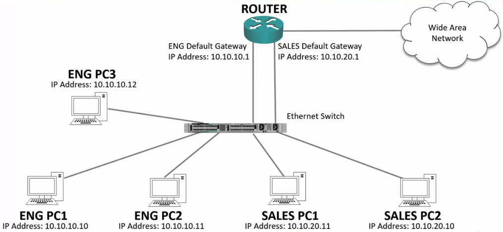
Same Subnet
- If the traffic is intended for a specific host that the switch has already learned, the switch will route that traffic directly to the connected port.
- Good for performance and security
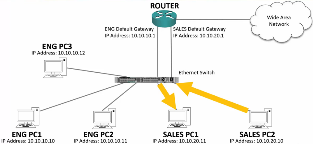
Different subnet
- The traffic will enter the switch, then to the Router because the Router’s IP is the default Gateway.
- The router, seeing the subnet is on that switch, will send it back down.
- The switch, knowing the MAC of the intended host will then send it directly to the port the host is connected on.
- Also good for performance and security
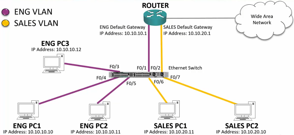
Broadcast Traffic
Example 1
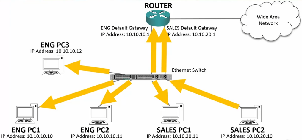
- Sales PC2 sends out an ARP.
- The switch sends the ARP out ALL PORTS.
- Switches flood broadcast traffic everywhere, including between different IP subnets
- The affects security because the traffic bypasses router or firewall Layer 3 security policies
- It affects performance because every end host has to process the traffic.
- It also affects performance by using bandwidth on links where the traffic is not required.
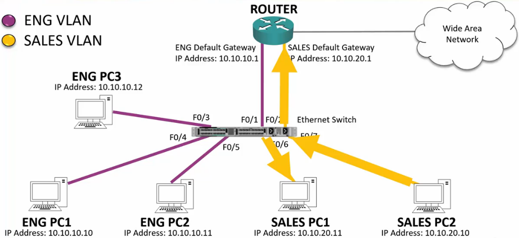
Example 2

VLAN Virtual Local Area Networks
- We can increase performance and security in the LAN by implementing VLANS on our switches.
- VLANS segment the LAN into separate broadcast domains at Layer 2
- There is typically a one-to-one relationship between an IP subnet and a VLAN.
VLAN Broadcasts
- Broadcasts are ONLY sent out ports that have been assigned to the VLAN
127. VLAN Access Ports and Configurations
https://www.udemy.com/cisco-icnd1/learn/lecture/8657044#content
- VLAN access ports are configured on the switch interfaces where end hosts are plugged in.
- Access ports are configured with one specific VLAN
- The configuration is all on the switch, the end host is not VLAN aware
- Switches only allow traffic within the same VLAN
- This creates smaller broadcast domains.
- Hosts in the same subnet should be on the same VLAN or they will not be able to communicate.
Default VLAN
- By default, all ports are in VLAN 1
VLAN Configuration
Create the VLAN
- VLANS require a unique number between 1 to 4094 (2^12 excluding 0 and 4095)
SW1(config)#vlan 10
SW1(config-vlan)#name Eng
Configure a single Switch Port
SW1(config)#interface FastEthernet 0/1
SW1(config-if)#switchport mode access
SW1(config-if)#switchport access vlan 10
Configure a range of Switch Ports
SW1(config)#interface range FastEthernet 0/1 - 5
SW1(config-if)#switchport mode access
SW1(config-if)#switchport access vlan 10
View Available VLANS
#show vlan brief
VLAN Name                             Status    Ports
---- -------------------------------- --------- -------------------------------
1    default                          active    Gi0/1, Gi0/2
100  10-0-0-0                         active    Fa0/1, Fa0/2, Fa0/3, Fa0/4
                                                Fa0/5, Fa0/6, Fa0/7, Fa0/8
                                                Fa0/9, Fa0/10, Fa0/11, Fa0/12
200  10-0-1-0                         active    Fa0/13, Fa0/14, Fa0/15, Fa0/16
                                                Fa0/17, Fa0/18, Fa0/19, Fa0/20
                                                Fa0/21, Fa0/22, Fa0/23, Fa0/24
1002 fddi-default                     act/unsup
1003 token-ring-default               act/unsup
1004 fddinet-default                  act/unsup
1005 trnet-default                    act/unsup
128. VLAN Access Ports Lab Demo
https://www.udemy.com/cisco-icnd1/learn/lecture/8657050#content
VLAN Lab
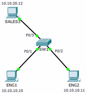
Initial Config
- All switchports on VLAN1
ENG1 Pings 10.10.10.11
ping ping ping
ENG1 Pings 10.10.10.255
ping ping ping
Config SW1-F0/1 VLAN 10
configure terminal
vlan 10
name ENG
int f0/1
switchport mode access
switchport access vlan 10
ENG1 Pings 10.10.10.11
Request time out.
ENG1 Pings 10.10.10.255
Request time out.
The ping request fail because F01 and F0/2 are on different VLANs
Config SW1-F0/2 VLAN 10
configure terminal
int f0/2
switchport mode access
switchport access vlan 10
ENG1 Pings 10.10.10.11
ping ping ping
ENG1 Pings 10.10.10.255
ping ping ping
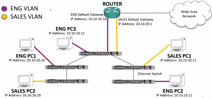
129. VLAN Trunk Ports
https://www.udemy.com/cisco-icnd1/learn/lecture/8657058#content
Trunk Ports: Links between switches
Dot1Q Trunks
- An access port carries traffic for one specific VLAN
- Dot1Q trunks are configured on the links between switches where we need to carry traffic for multiple VLANs
- ISL (Inter-Switch Link) was a Cisco proprietary trunking protocol, but is now obsolete.
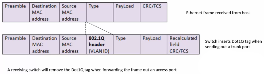
- When the switch forwards traffic to another switch, it tags the Layer 2 Dot1Q header with the correct VLAN
- The tag is inserted into the Layer 2 header. See ‘Dot1Q Format’ below.
- The receiving switch will only forward the traffic out ports that are in that VLAN
- The switch removes the Dot1Q tag from the Ethernet frame when it sends it to the end host.
Dot1Q Format
Example
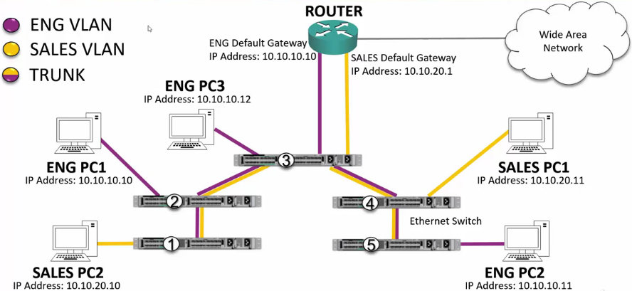
- Sales PC2 sends out a broadcast message.
- There are no other port configured on SW1’s Sales VLAN, but it does have a trunk port, so it sends the request on that port.
- Before it sends, it ‘injects’ the header with the 12bit VLAN number
- SW2 receives the frame and removes the tag from header.
- Since there are no Sales VLANs available, it re-tags the header and passes the traffic through its trunk port to SW3.
- SW3 receives the message and removes the tag.
- It sees it has a port configured for the Sales VLAN and passes the frame through that port.
- It also sees it has Trunk connection to SW4, so it re-adds the VLAN data and sends the frame to SW4.
- SW4 receives the message and removes the tag.
- It sees it has a port configured for the Sales VLAN and passes the frame through that port.
- It also sees it has Trunk connection to SW5, so it re-adds the VLAN data and sends the message to SW5.
- SW4 receives the message and removes the tag.
- SW5 has no additional Trunk ports and no Sales VLANs so it drops the frame.
Hypervisors – VLAN Aware Hosts
(Not required for the exam)
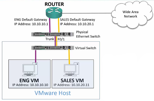
- End hosts are typically members of only one VLAN and are not VLAN aware.
- A special case is virtualized hosts, where there are virual machines in different IP subnets on the host.
- In this case, we need to trunk the VLANS down to the host.
Trunk Port Configuration
SW1(config)#interface fastethernet 0/24
SW1(config-if)#description Trunk to SW2
SW1(config-if)#switchport mode trunk
SW1(config-if)#switchport trunk encapsulation dot1q
Note
- Older switches still support ISL
- Newer switches do not, but you still need to specify ‘dot1q’ protocol.
The Native VLAN
- The switch needs to know which VLAN to assign to any traffic that comes in untagged on a trunk port.
- This used to be required when a switch was connected to a hub.
- Hubs are Layer 1 devices and are not VLAN aware
- The Native VLAN is used for this
- The default Native VLAN is VLAN 1
- Using VLAN 1 poses some security risks, so it is best practice to change it to an unused VLAN
- The Native VLAN must match on both sides of the trunk for it to come up.
Native VLAN Configuration
SW1(config)#VLAN 199
SW1(config-vlan)#name Native
SW1(config-vlan)#interface gigabitethernet 0/1
SW1(config-if)#description Trunk to SW2
SW1(config-if)#switchport mode trunk
SW1(config-if)#switchport trunk encapsulation dot1q
SW1(config-if)#switchport trunk native vlan 199
** It appears there is no need to assign the encapulation. In fact, my switch would not accept the encapsulation command!
Verify Trunking Settings
Know this for the exam!
SW1#show interface g0/1 switchport
Name: Gi0/1
Switchport: Enabled
Administrative Mode: trunk
Operational Mode: down
Administrative Trunking Encapsulation: dot1q
Negotiation of Trunking: On
Access Mode VLAN: 1 (default)
Trunking Native Mode VLAN: 199 (Native)
Voice VLAN: none
Administrative private-vlan host-association: none
Administrative private-vlan mapping: none
Administrative private-vlan trunk native VLAN: none
Administrative private-vlan trunk encapsulation: dot1q
Administrative private-vlan trunk normal VLANs: none
Administrative private-vlan trunk private VLANs: none
Operational private-vlan: none
Trunking VLANs Enabled: ALL
Pruning VLANs Enabled: 2-1001
Capture Mode Disabled
Capture VLANs Allowed: ALL
Protected: false
Unknown unicast blocked: disabled
Unknown multicast blocked: disabled
Appliance trust: none
Limiting Allowed VLANs
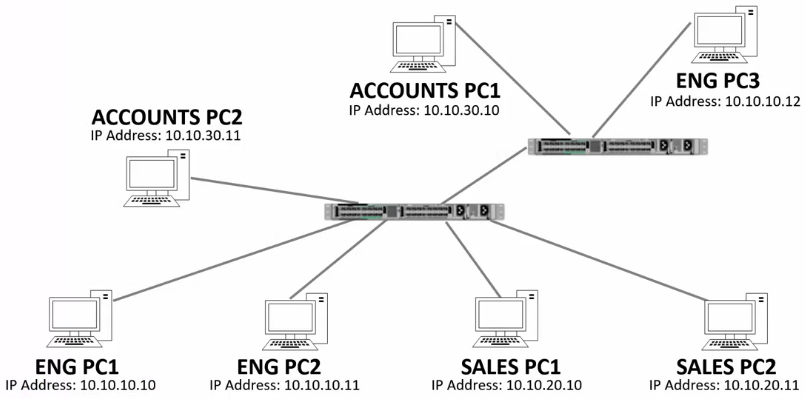
- In the example above:
- SW1 is connected to:
- VLAN10 (Eng)
- VLAN 20 (Sales)
- VLAN 30 (Accounts)
- SW2 is connected to:
- Eng
- Accounts
- SW1 is connected to:
- Since there is no need for Sales VLAN traffic to pass through this trunk, use the following configuration:
interface g 0/1
switchport trunk allowed vlan 10, 30
130. VLAN Trunks Lab Demo
https://www.udemy.com/cisco-icnd1/learn/lecture/8657064#content
Lab Demo
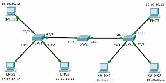
Init Setup
- SW1 configured:
- VLAN Eng: 0/1, 0/2
- VLAN Sales: 0/3
- G0/1 unconfigured
- switchport mode access
- vlan 1
Complete Configuration of SW1
Configure the Native VLAN
- Name can be anything
- Choose a vlan you are not using in production
SW1#conf t
SW1(config)#vlan 199
SW1(config-vlan)#name Native
Configure SW1-G0/1 as a trunk to SW2
- The dot1q encapsulation command failed since only dot1q is allowed on this switch.
SW1(config)#int g0/1
SW1(config-if)#desc Trunk To SW2
SW1(config-if)#switchport mode trunk
SW1(config-if)#switchport trunk encapsulation dot1q
                                ^
% Invalid input detected at '^' marker.
SW1(config-if)#switchport trunk native vlan 199
SW1(config-if)#no shutdown
Configure SW2
Configure Eng, Sales and Native
SW2#configure terminal
SW2#(config)#vlan 10
SW2(config-vlan)#name Eng
SW2(config-vlan)#vlan 20
SW2(config-vlan)#name Sales
SW2(config-vlan)#vlan 199
SW2(config-vlan)#name Native
Configure SW2-G0/1 as a trunk to SW1
SW2(config)#int g0/1
SW2(config-if)#desc Trunk To SW2
SW2(config-if)#switchport mode trunk
SW2(config-if)#switchport trunk encapsulation dot1q
SW2(config-if)#switchport trunk native vlan 199
#SW2(config-if)#switchport trunk allowed vlan 10,20
SW2(config-if)#no shutdown
Configure SW2-G0/2 as a trunk to SW3
SW2(config)#int g0/2
SW2(config-if)#desc Trunk To SW3
SW2(config-if)#switchport mode trunk
SW2(config-if)#switchport trunk encapsulation dot1q
SW2(config-if)#switchport trunk native vlan 199
SW2(config-if)#no shutdown
Configure SW3
Configure the Eng, Sales and Native VLANs
SW3#conf t
SW3(config)#vlan 10
SW3(config-vlan)#name Eng
SW3(config-vlan)#vlan 20
SW3(config-vlan)#name Sales
SW3(config-vlan)#vlan 199
SW3(config-vlan)#name Nativ
Configure SW3-G0/2 as a trunk to SW2
SW3(config)#int g0/2
SW3(config-if)#desc Trunk To SW2
SW3(config-if)#switchport trunk encapsulation dot1q
SW3(config-if)#switchport mode trunk
SW3(config-if)#switchport trunk native vlan 199
SW3(config-if)#no shutdown
Configure SW3 Access Po
SW3(config)#int f0/1
SW3(config-if)#switchport mode access
SW3(config-if)#switchport access vlan 200
SW3(config)#int f0/2
SW3(config-if)#switchport mode access
SW3(config-if)#switchport access vlan 200
SW3(config)#int f0/3
SW3(config-if)#switchport mode access
SW3(config-if)#switchport access vlan 100
131. VLAN Configuration Lab Exercises
https://www.udemy.com/cisco-icnd1/learn/lecture/8657070#overview
VLAN and Inter-VLAN routing lab exercises are included together at the end of the next section. Please watch the Inter-VLAN routing section next before completing the labs.