< Section 16 | Home | Section 18 >
44% Complete!
103: Dynamic Routing Protocols – Introduction
https://www.udemy.com/cisco-icnd1/learn/lecture/8605430#overview
Discuss different types of protocols then how different routes make it to the routing table.
104: Dynamic Routing Protocols vs Static Routes
https://www.udemy.com/cisco-icnd1/learn/lecture/8605432#overview
https://www.udemy.com/course/ccna-complete/learn/lecture/7840142#overview
Dynamic Routing Protocols
- When a routing protocol is used, routers automatically advertise their best paths to known networks to each other
- Routers use this information to determine their own best path to the known destinations.
- When the state of the network changes, such as a link going down or a new subnet being added, the routers update each other.
- Routers will automatically calculate a new best path and update the routing table if the network changes.
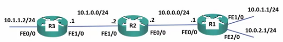
- R2 and R3 are not connected to 10.0.1.0/24 nor 10.0.2.0/24 so they are not aware of them.
- This will require configuring static routing which would require manual entries
- Or we can use dynamic routing protocols.
- We configure R1, R2 and R3 dynamically so they will share their routes with each other.
- R1 to R2: You can access 10.0.1.0/24 and 10.0.2.0/24 through me.
- R2 knows this came from R1 from IP 10.0.0.1/24
R2 Routing Table
10.0.0.0/24 Connected FE0/0
10.1.0.0/24 Connected FE1/0
10.0.1.0/24 10.0.0.1 FE0/0
10.0.2.0/24 10.0.0.1 FE0/0
- R2 now tells R3 its available networks
- 10.0.0.0/24
- 10.0.1.0/24
- 10.0.2.0/24
R3 Routing Table
10.1.1.0/24 Connected FE0/0
10.1.0.0/24 Connected FE1/0
10.0.0.0/24 10.1.0.2 FE1/0
10.0.1.0/24 10.1.0.2 FE1/0
10.0.2.0/24 10.1.0.2 FE1/0
This also occurs in the opposite direction so R1 will learn R2’s routes and R1 and R2 will both learn R3’s routes.
Summary Routes
- R1 can be configured to send Summary routes instead of the individual routes.
- R1 to R2: You can access 10.0.0.0/16 though me
- Summary routes lead to less memory usage in routers as their routing tables contain less routes.
- They also lead to less CPU usage as changes in the network only affect other routers in the same area
- For example: If the link on R1 to the 10.0.11.1/24 network goes down, R2 will lose its route there and try to compute a new path.
- This will require cpu resources to complete this
- R3 will not be affected as its summary route to 10.0.0.0/16 is unchanged (through R2)
Dynamic Routing Protocols vs Static Routes
- Dynamic routing protocols are more scalable than admin defined static routes.
- Using purely static routes is only feasible in very small environments.
Dynamic Routing Protocol Advantages
- Routers automatically advertise available subnets to each other without the4 admin. having to manually enter every route on every router.
- If a subnet is added or removed, the routers will automatically discover the changes and update their routing tables.
- If the best path to a subnet goes down, routers automatically discover this and will calculate a new best path if one is available.
- If a Static route fails, it cannot self recover, so it will require a lot of admin work again.
Dynamic Routing Protocols vs Static Routes continued
- It is common to find a mix of both static and dynamic routing in the real world
- In this case, dynamic routing carries the bulk of the network information
- Static routes can be applied on an as-needed basis.
- For example: For backup purposes or for a static route to access the Internet (which will typically be injected into the dynamic routing protocol and advertised to the rest of the routers).
105: Dynamic Routing Protocols Lab Demo
https://www.udemy.com/cisco-icnd1/learn/lecture/8605464#overview

- Will be using RIP Router Information Protocol.
- Easiest to copy common configurations into a text editor, then copy/paste them in.
Debug Commands
- Debug commands are updated in real time
- Like Show commands, Debug commands are entered at the enable prompt.
debug ip rip
- The system starts displaying messages in real time.
- You can see both sending and receiving information from all connected routers
debug ip rip
This should work with any routing protocol
debug ip <routing protocol>
Disable debugging on all protocols
undebug all
106: Routing Protocol Types
https://www.udemy.com/cisco-icnd1/learn/lecture/8605466#overview

Routing Protocol Types
- Routing protocol types can be split into two main types:
- Interior gateway protocols (IGPs)
- Exterior gateway protocols (EGPs)
- Interior gateway protocols are used for routing within an organization
- Exterior gateway protocols are used for routing between organizations over the Internet.
- The only EGP in use today is BGP (Border Gateway Protocol)
Interior Gateway protocols
- Interior gateway protocols can be split into two main types:
- Distance vector routing protocols
- Link State routing protocols
Distance Vector Routing Protocols
- In Distance Vector protocols, each router sends its directly connected neighbors a list of all its known networks along with its own distance to each of those networks.
- Distance vector routing protocols do not advertise the entire network topology.
- A router only knows its directly connected neighbors and the lists of networks those neighbors have advertised. It doesn’t have detailed topology information beyond its directly connected neighbors.
- Distance Vector routing protocols are often called ‘Routing by rumor’.
- “I know of a route that has been passed along to me”
Link State Routing Protocols
- In Link State routing protocols, each router describes itself and its interfaces to its directly connected neighbors
- This information passes unchanged from one router to another.
- Every router learns the full picture of the network including every router, its interfaces and what they connect to.
- “I know of a route, here is the exact information that was provided to me.”
- While this protocol is generally more reliable, it also puts a greater strain on the routers because it stores a lot more information.
Commonly used routing protocols
- Interior
- Distance Vector
- RIP: Routing Information Protocol
- EIGRP: Enhanced Interior Gateway Routing Protocol
- Cisco proprietary
- Link State
- OSPF: Open Shortest Path First
- IS-IS: Intermediate System – Intermediate System
- Distance Vector
- Exterior
- Path Vector
- BGP: Border Gateway Protocol
- Path Vector
Interior Gateway Protocols
- All IGPs do the same job: Advertise routes within an organization and determine the best path or paths.
- An organization will typically pick one of the IGPs
- If an organization has multiple IGPs in effect (for example, because of a merger), information can be redistributed between them.
- This can get messy, so this should be avoided if possible.
107: Routing Protocol Types Lab Demo
https://www.udemy.com/cisco-icnd1/learn/lecture/8605470?start=0#overview
Comparison between Distance Vector and Link State Routing Protocols
R1#show ip protocols
*** IP Routing is NSF aware ***

Routing Protocol is "rip"
...
- Learned routing information is stored in the routing protocol database.
- show ip rip database
- show ip ospf database
- …
- The ‘best’ routes are added to the Routing Table.
With Routing Protocols, 3 things happen.
- Routers form an adjacency between each other
- They exchange routes with each other
- These are stored in the Routing Protocol Database
- The ‘best’ routes are added to the Routing Table
108: Routing Protocol Metrics
https://www.udemy.com/cisco-icnd1/learn/lecture/8605472#overview
Metric
- A router may receive multiple possible paths to get to a destination network.
- Only the best path will make it into the routing table and be used
- The different IGPs use different methods to calculate the best path to a destination network..
- Each possible path will be assigned a ‘metric’ value by the routing protocol which indicates how preferred the path is.
- The lowest metric value is preferred.
- Distance Vector routers advertise to each other the networks they know about, and their metric to get to each of them.
- Link State routers advertise all the links in their area of the network to each other.
- Each router will take this information and then make an independent calculation of its own best path to get to each destination.
- If the best path to a destination is lost (for example, a link went down) it will be removed from the routing table and replaced with the next best route if one is available.
RIP Metric – Hop Count
- Routing Information Protocol (Distance Vector)
- RIP uses Hop Count as the metric
- The maximum hop count by default is 15. Paths which are more than 15 hops away are marked as unreachable..
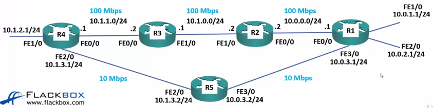
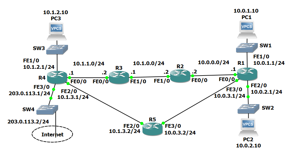
- Path R4 > 5 > 1 will be preferred for 10.0.1.0/24 in the example above.
- Note the links between R4-R5 and R5-R1 are 10Mbps, so this is actually a much slower route!
- RIP is typically used only in small or test environments.
OSPF Metric – Cost
- Open Shortest Path First (Link State)
- OSPF uses ‘cost’ as the metric, which is automatically derived from interface bandwidth by default.
- You can manually configure the cost of links if you want to manipulate the path.
- Path R4 > 3 > 2 > 1 will be preferred for 10.0.1.0/25 in RIP example above.
IS-IS Metric – Cost
- Intermediate System – Intermediate System (Link State)
- IS-IS uses ‘cost’ as the metric, but it is not automatically derived from interface bandwidth. All links have an equal cost by default.
- You can manually configure the cost of links if you want to manipulate the path
- You do not have this ability in RIP
- If you do not manually set the link costs then the path with the lowest hop count will be used.
- Path R4 > 5 > 1 would be preferred for 10.0.1.0/24 in the RIP example above.
EIGRP
- Enhanced Interior Gateway Routing Protocol (Distance Vector)
- EIGRP uses the bandwidth and delay of links to calculate the metric.
- Load and reliability can also be considered but are ignored by default
- A fixed delay value is used based on the interface bandwidth. The protocol does not dynamically measure the current delay.
- You can manually configure the delay on links if you want to manipulate the path.
- Path R4 > 3 > 2 > 1 would be preferred for 10.0.1.0/24 in the RIP example above.
Choosing a Routing Protocol
- RIP uses hop count and has a default maximum metric of 15. it is not usually used in production networks because of its scalability limitations.
- EIGRP is very easy to maintain, calculate changes quickly and its metric calculation will normally choose the best path by default. it is typically only supported on Cisco routers, however.
- OSPF’s metric calculation will typically choose the best path by default. it is an open standard which is supported by all routers and is the most commonly deployed IGP today. It is, however, more complicated to maintain than EIGRP.
- IS-IS links need to be manually configured or it will use hop count to determine the best path. it is typically only used in Service Provider networks or large organizations with their own MPLS network who choose it because of its scalability.
109: Routing Protocol Metrics Lab Demo
https://www.udemy.com/cisco-icnd1/learn/lecture/8605474#overview
Initial Configuration
- Interfaces configured with IPs
- No routes
RIP Configuration
configure terminal
router rip
network 10.0.0.0
no auto-summary
Path from R1 to R4 (10.1.2.0/24) via R5
R 10.1.2.0/24 [120/2] via 10.0.3.2, 00:00:20, FastEthernet3/0
Shutdown FA3/0
R1(config)#int f3/0
R1(conf-if)#shutdown
R1(conf-if)#end
R1#show ip route
...
R   10.1.2.0/24 [120/2] via 10.0.0.2, 00:00:20, FastEthernet0/0
IS-IS
This isn’t tested much for CCNA because it is seldom used outside of Service Provider networks. If you study for Service Provider certification, you’ll will be tested heavily in IS-IS
Note: Each router needs a unique net id, so R2=.0002.00, R3=.0003.00, etc.
configure terminal
router isis
  net 49.0001.0000.0000.0001.00
!
interface f0/0
 ip router isis
!
interface f1/0
 ip router isis
!
interface f2/0
 ip router isis
!
interface f3/0
 ip router isis
- This will replace the RIP configuration in the routing table.
R1#show ip route
...
i L1   10.1.2.0/24 [115/2] via 10.0.3.2, 00:00:20https://www.udemy.com/course/ccna-complete/learn/lecture/7840142#overview, FastEthernet3/0
- Same as RIP because no costs have been set on the links.
Shutdown FA3/0
R1(config)#int f3/0
R1(conf-if)#shutdown
R1(conf-if)#end
R1#show ip route
...
i l1   10.1.2.0/24 [120/2] via 10.0.0.2, 00:00:20, FastEthernet0/0
OSPF
configure terminal
router ospf 1
network 10.0.0.0.0 0.255.255.255 area 0
ip show route
...
O        10.1.2.0/24 [110/4] via 10.0.0.2, 00:00:58, FastEthernet0/0
i L1  203.0.113.0/24 [115/30] via 10.0.3.2, 00:2:25, FastEthernet3/0
* 203 route was not included in the OSPF search, so the IS-IS remained!
Since OSPF does include speed as a cost measurement, it routed the fastest route vs. the shortest.
Shutdown FA0/0
R1(config)#int f0/0
R1(conf-if)#shutdown
R1(conf-if)#end
R1#show ip route
...
O      10.1.2.0/24 [110/21] via 10.0.3.2, 00:00:06, FastEthernet3/0
EIGRP
router eigrp 100
no auto-summary
network 10.0.0.0 0.255.255.255
R1#show ip route
...
D      10.1.2.0/24 [90/35840] via 10.0.0.2, 00:00:11, FastEthernet0/0
Shutdown FA0/0
R1(config)#int f0/0
R1(conf-if)#shutdown
R1(conf-if)#end
R1#show ip route
...
D      10.1.2.0/24 [90/263680] via 10.0.3.2, 00:00:13, FastEthernet3/0
110: Equal Cost Multi Path
https://www.udemy.com/cisco-icnd1/learn/lecture/8605480#overview
Equal Cost Multi Path (ECMP)
(This is really the same as load balancing)
- If multiple paths to a destination have an equal metric, the router will enter all of the paths into the routing table.
- ECMP will load balance the outbound traffic to the destination over the different paths.
- All IGP routing protocols will perform ECMP by default.
- EIGRP is the only routing protocol which is capable of UnEqual Cost Multi Path. It must be manually configured to support this.
111: Equal Cost Multi Path Lab Demo
https://www.udemy.com/cisco-icnd1/learn/lecture/8605482#overview

RIP Load balances R4 > R1 across both routes
R4#show ip route
...
R     10.0.1.0/24 [120/3] via 10.1.3.2, 00:00:04, FastEthernet2/0
                  [120/3] via 10.1.1.2, 00:00:04, FastEthernet0/0
R     10.0.2.0/24 [120/3] via 10.1.3.2, 00:00:04, FastEthernet2/0
                  [120/3] via 10.1.1.2, 00:00:04, FastEthernet0/0
OSPF only shows 1 route for R4 > R1
Same hop count, but different costs due to speed differences.
R4#show ip route
...
O     10.0.1.0/24 [110/3] via 10.1.1.2, 00:00:04, FastEthernet0/0
O     10.0.2.0/24 [110/3] via 10.1.1.2, 00:00:04, FastEthernet0/0
OSPF load balances R4 > R1
Edit both 10Mbps connections to be 100Mbps
R4#show ip route
...
O     10.0.1.0/24 [110/3] via 10.1.3.2, 00:00:04, FastEthernet2/0
                  [110/3] via 10.1.1.2, 00:00:04, FastEthernet0/0
O     10.0.2.0/24 [110/3] via 10.1.3.2, 00:00:04, FastEthernet2/0
                  [110/3] via 10.1.1.2, 00:00:04, FastEthernet0/0
112: Administrative Distance
https://www.udemy.com/cisco-icnd1/learn/lecture/8605484#overview
Overview (My notes)
- “How trusted is the routing protocol that provides a route”
- Used when receiving routes to the same destination via different protocols.
- Lowest # wins
Metric
- A router will typically only learn routes to a particular destination from a single routing protocol.
- When multiple routes to a destination are learned through a routing protocol, the router will install the path or paths with the best (lowest) metric into the routing table.
- Different routing protocols use different methods to calculate the metric.
- RIP Example:
- Path A>B>C>D has a hop count of 3
- Path A>B>D has a hop count of 2
- A>B>D will be used.
- OSPF Example:
- Path A>B>C>D has a cost of 60
- Path A>B>D has a cost of 100
- A>B>C>D will be used.
- RIP Example:
Administrative Distance
- If paths to the same destination are received from different routing protocols, their metrics cannot be compared.
- For example: a RIP count of 5 cannot be compared to an OSPF cost of 60. The comparison is meaningless because the routing protocols calculate the metric in completely different ways
- The router must use a different method to choose when routes to the same destination are received from different routing protocols.
- The Administrative Distance (AD) is used for this.
- The Administrative Distance is a measure of how trusted the routing protocol is.
- If routes to the same destination are received via different routing protocols, the protocol with the best (lowest) AD wins.
| Route Source | Default AD |
|---|---|
| Connected Interface | 0 |
| Static Route | 1 |
| External BGP | 20 |
| EIGRP | 90 |
| OSPF | 110 |
| IS-IS | 115 |
| RIP | 120 |
Administrative Distance and Metric
- Administrative Distance is used to choose between multiple paths learned via different routing protocols.
- Metric is used to choose between multiple paths learned via. the same protocol.
- The Administrative Distance is considered first to narrow the choice down to the single best routing protocol.
- The Metric is then considered to choose the best path or paths which make it into the routing table.
Floating Static Routes
- If the best path to a destination is lost (example, the link goes down), it will be removed from the routing table and replaced with the next best route.
- We might want to configure a static route as a backup for the route learned via a routing protocol.
- A problem is that static routes have a default Administrative Distance of 1, which will always be preferred over routes learned via an IGP.
- We can change the default AD value when setting the static route
R1(config)#ip route 10.0.1.0 255.255.255 10.1.3.2 115
- Note:
- The AD value must be higher than the IGR AD value
- You must also have a return route!
- This can also be used to set priorities in Static Routes
R1(config)#ip route 10.0.1.0 255.255.255 10.1.3.2R1(config)#ip route 10.0.1.0 255.255.255 10.2.1.2 5
113: Administrative Distance Lab Demo
https://www.udemy.com/cisco-icnd1/learn/lecture/8605486#overview
Nothing new here…
114: Loopback Interfaces
https://www.udemy.com/cisco-icnd1/learn/lecture/8605498#overview
- Loopback interfaces are logical interfaces
- They allow you to assign an IP address to a router or L3 switch, which is not tied to a physical interface
- Because they don’t have any physical attributes which can fail, loopback interfaces never go down.
- Loopbacks are logical so they cannot be physically in the same subnet as other devices, so they are usually assigned a /32 subnet mask to avoid wasting IP addresses.
Loopback Interface Uses
- It is best practice to assign a loopback interface to your routers
- The loopback is commonly used for traffic that terminates on the router itself.
- This could be management traffic, VoIP, BGP peering, etc.
- Ths provides redundancy if there are multiple paths to the router.
- The loopback is also used to identify the router (Router ID) in OSPF.
- The same loopback interface is usually used for multiple tasks (for example management abd BGP)
- Multiple loopbacks can be configured. This is not common and usually only done where another, separate loopback is required for a special use case.
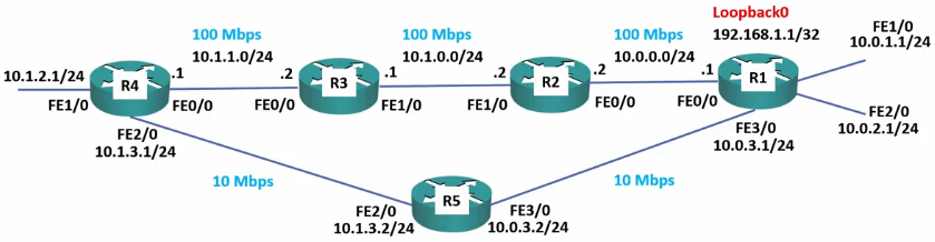
Loopback Interface Example
- Access PC is on 10.1.2.0 subnet (R4) and need to connect to R1 to manage it.
- If the top path goes down you cannot connect to 10.0.0.1
- If the bottom path goes down, you cannot connect to 10.0.3.1
- Add interface Loopback 0 with IP Address 192.168.1.1/32
- Advertise 192.168.1.1/32 in the routing protocol
- R4 learns both paths to 192.168.1.1
- You can still connect to 192.168.1.1 even if the top or bottom path fails.
Loopback Interface Lab
R1 Configuration
R1#configure terminal
R1(config)#interface loopback 0
R1(config-if)#
192.168.1.1 255.255.255.255
no shutdown
115: Adjacencies and Passive Interfaces
https://www.udemy.com/cisco-icnd1/learn/lecture/8605510#overview
Adjacencies
- IGP routing protocols are configured under global configuration mode and enabled on individual interfaces.
- When the routing protocol is enabled on an interface, the router will look for other devices on the link which are also running the routing protocol
- The router does this by sending out and listening for hello packets.
- When a matching peer is found, the routers form an adjacency with each other.
- They then exchange routing information
- Modern routing protocols use multicast for the hello packets.
- This is more efficient than broadcast which was used by earlier protocols
- Only routers which are running the same routing protocol will process the packet.
Adjacency Example

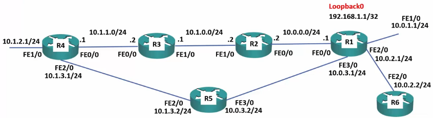
- The IP subnets configured on the interfaces which are enabled for the routing protocol will be included in its updates.
- For example: R1 has a routing protocol enabled on the Loopback0 interface and FastEthernet0/0 and 1/0
- The routing protocol is not enabled on F2/0
- RC belongs to a partner organization we do not want to send internal network information to.
- R1 will send out and listen for hello packets on the Loopback0 interface and F0/0 and F1/0
- It will form adjacencies with any routers running the same protocol on those links. – RA and RB
- It will NOT send out or listen for hello packets on F2/0
- It will NOT form an adjacency with RC
- Instead, we will use static routes for the extranet traffic with RC
- R1 will advertise IP subnets to RA and RB
- 10.0.0.0/24
- 10.0.1.0/24
- 192.168.1.1/32
- R1 will not advertise 10.0.2.0/24
- RA and RB will not learn routes to 10.0.2.0/24
Passive Interfaces
- Passive Interfaces allow you to include an IP subnet in the routing protocol without sending updates out of the interface.
- If F2/0 is configured as a passive interface, RA and RB will learn routes to 10.0.2.0/24, but internal network information will not be send to RC
Loopback Passive Interfaces
- It is best practice to configure loopback interfaces as Passive Interfaces.
- It is impossible to form an adjacency on a loopback interface because they are not physical interfaces.
- Making the loopback passive means that it will be advertised by the routing protocol, but will not waste resources send out and listening for hello packets.
Passive Interface Use Cases
- Loopback interfaces
- Physical interfaces where the devices on the other side belongs to another organization.
- We do not want to send out routing information to them.
- We do want our internal devices to know about the link.
116: Adjacencies and Passive interfaces Lab Demo
https://www.udemy.com/cisco-icnd1/learn/lecture/8605514#overview
How to configure passive interfaces
- R1 – R5 are all internal
- R6 is at a partner.
- We do not want to form an adjacency with R6
- R1-Loopback0 should also be configured as passive.
Starting Config
- All IP interfaces configured
- R1 Loopback0 not configured
- RIP enabled on R2 – R5
- No routing protocols enabled on R1
- R4 cannot see 10.0.1.0/24
Configure R1 Loopback 0
R1(config)#interface loopback 0
R1(config-if)#ip address 192.168.1.1 255.255.255.255
R1(config-if)#no shutdown
R1(configif)#exit
Configure RIP on R1
R1(config)#router rip
R1(config-router)#version 2
R1(config-router)#no auto-summary
R1(config-router)#passive-interface loop0
R1(config-router)#passive-interface f2/0
R1(config-router)#exit
Enable RIP on the desired interfaces
R1(config)#router rip
R1(config-router)#network 192.168.1.1
R1(config-router)#network 10.0.0.0
R1(config-router)#end
After a few moments, RIP should propagate.
Verify routes can be seen on R4
R4#show ip route
...
R      10.0.1.0/24 [120/2] via 10.1.3.2, 00:00:03, FastEthernet2/0
R      10.0.2.0/24 [120/2] via 10.1.3.2, 00:00:03, FastEthernet2/0
R      10.0.3.0/24 [120/2] via 10.1.3.2, 00:00:03, FastEthernet2/0
...
R      192.168.1.1 [120/2] via 10.1.3.2, 00:00:03, FastEthernet2/0
Check R6 (Partner Network) to see if it learned any routes
R6#show ip route
(only locally connected routes available)
117: Dynamic Routing Protocols – Lab Exercises
https://www.udemy.com/cisco-icnd1/learn/lecture/8605520#overview
17 Dynamic Routing Protocols Lab Exercise
17 Dynamic Routing Protocols Answer Key
Routing Protocol Updates
1.Configure RIP
configure terminal
router rip
network 10.0.0.0
no auto-summary
end
2. debug ip rip
- RIP: sending v1 update to 255.255.255.255 (Broadcast!)
3. configure terminal
router rip
version 2
4. RIP: sending v2 update to 224.0.0.9 (Multicast?)
5. #no debug ip rip
6. show ip route
- Confirmed
7. These routes have the same AD/Metric [120/2]
Comparing Routing Protocols
8.
R1#show ip rip database
10.0.0.0/8    auto-summary
10.0.0.0/24    directly connected, FastEthernet0/0
10.0.1.0/24    directly connected, FastEthernet1/0
10.0.2.0/24    directly connected, FastEthernet2/0
10.0.3.0/24    directly connected, FastEthernet3/0
10.1.0.0/24
    [1] via 10.0.0.2, 00:00:18, FastEthernet0/0
10.1.1.0/24
    [2] via 10.0.3.2, 00:00:15, FastEthernet3/0
    [2] via 10.0.0.2, 00:00:18, FastEthernet0/0
10.1.2.0/24
    [2] via 10.0.3.2, 00:00:15, FastEthernet3/0
10.1.3.0/24
    [1] via 10.0.3.2, 00:00:15, FastEthernet3/0
9.
configure terminal
router ospf 1
network 10.0.0.0 0.255.255.255 area 0
end
10. No. OSPF has a lower Administrative Distance than RIP so it takes presidence.
11. While that route has to identical routes per hop count, the path down F0/0 has faster links, therefore it has a lower metric score and is the better route to use.
12. Done. All routes via R1-f0/0 (excluding 10.0.0.0/24) will change to R1-f3/0
13.
show ip route
      10.0.0.0/8 is variably subnetted, 12 subnets, 2 masks
C        10.0.0.0/24 is directly connected, FastEthernet0/0
L        10.0.0.1/32 is directly connected, FastEthernet0/0
C        10.0.1.0/24 is directly connected, FastEthernet1/0
L        10.0.1.1/32 is directly connected, FastEthernet1/0
C        10.0.2.0/24 is directly connected, FastEthernet2/0
L        10.0.2.1/32 is directly connected, FastEthernet2/0
C        10.0.3.0/24 is directly connected, FastEthernet3/0
L        10.0.3.1/32 is directly connected, FastEthernet3/0
O        10.1.0.0/24 [110/22] via 10.0.3.2, 00:01:42, FastEthernet3/0
O        10.1.1.0/24 [110/21] via 10.0.3.2, 00:01:42, FastEthernet3/0
O        10.1.2.0/24 [110/21] via 10.0.3.2, 00:01:42, FastEthernet3/0
O        10.1.3.0/24 [110/20] via 10.0.3.2, 00:01:42, FastEthernet3/0
14. The routes’ Metric have increased.
15. OSPF contains data from all routers. RIP now only contains locally connected routes.
#show ip ospf database

OSPF Router with ID (10.0.3.1) (Process ID 1)

Router Link States (Area 0)

Link ID ADV Router Age Seq# Checksum Link count
10.0.3.1 10.0.3.1 137 0x80000003 0x00A5EA 4
10.1.0.2 10.1.0.2 118 0x80000002 0x002AAD 2
10.1.1.2 10.1.1.2 107 0x80000003 0x00626F 2
10.1.3.2 10.1.3.2 96 0x80000002 0x008A29 2
203.0.113.1 203.0.113.1 97 0x80000003 0x00AA9A 3

#show ip rip database
10.0.0.0/8    auto-summary
10.0.0.0/24    directly connected, FastEthernet0/0
10.0.1.0/24    directly connected, FastEthernet1/0
10.0.2.0/24    directly connected, FastEthernet2/0
10.0.3.0/24    directly connected, FastEthernet3/0
- The other routers are sending their best routes?
Routing Metrics and Administrative Distance
16. done
17. Yes – via R5
18. 2
19. R2-F0/0 was shut down
20.
R2#conf t
int f0/0
no shutdown
21. Enter the commands below on each router to provision a basic EIGRP configuration and enable EIGRP on every interface.
conf t
router eigrp 100
no auto-summary
network 10.0.0.0 0.255.255.255
end
show ip protocols
22. What do you expect to change in the routing tables?
- All non-connected routes to be replaced with EIGRP routes.
- New Administrative Distances and Metrics
23. Verify the changes to the routeing table on R1
show ip route
      10.0.0.0/8 is variably subnetted, 12 subnets, 2 masks
C        10.0.0.0/24 is directly connected, FastEthernet0/0
L        10.0.0.1/32 is directly connected, FastEthernet0/0
C        10.0.1.0/24 is directly connected, FastEthernet1/0
L        10.0.1.1/32 is directly connected, FastEthernet1/0
C        10.0.2.0/24 is directly connected, FastEthernet2/0
L        10.0.2.1/32 is directly connected, FastEthernet2/0
C        10.0.3.0/24 is directly connected, FastEthernet3/0
L        10.0.3.1/32 is directly connected, FastEthernet3/0
D        10.1.0.0/24 [90/30720] via 10.0.0.2, 00:00:51, FastEthernet0/0
D        10.1.1.0/24 [90/33280] via 10.0.0.2, 00:00:11, FastEthernet0/0
D        10.1.2.0/24 [90/35840] via 10.0.0.2, 00:00:11, FastEthernet0/0
D        10.1.3.0/24 [90/261120] via 10.0.3.2, 00:00:11, FastEthernet3/0
24. What is the metric to the 10.1.1.0/24 network on R1?
- 33280
25. Why is there only one route to the 10.1.1.0/24 network on R1?
- The displayed route has a lower metric (cost) than the alternative.
26. Disable RIP and EIGRP on R5 with the commands below.
R5#
conf t
no router rip
no router eigrp 100
end
27. Configure the network so that there is still connectivity between all subnets if the link between R1 and R2 goes down. Accomplish this with six commands. Do not enable EIGRP on R5 but note that the routing protocol is expected to be enabled there in the future.
R1(config)#ip route 10.1.0.0 255.255.0.0 10.0.3.2 95
R2(config)#ip route 10.0.0.0 255.255.0.0 10.1.0.1 95
R3(config)#ip route 10.0.0.0 255.255.0.0 10.1.1.1 95
R4(config)#ip route 10.0.0.0 255.255.0.0 10.1.3.2 95
R5(config)#ip route 10.0.0.0 255.255.0.0 10.0.3.1 95
R5(config)#ip route 10.1.0.0 255.255.0.0 10.1.3.1 95
28. What changes do you expect to see to the routing table on R1?
- The summary route will not be used because it has the smaller network prefix.
29. Verify the changes to the routing table on R1.
R1#show ip route
      10.0.0.0/8 is variably subnetted, 13 subnets, 3 masks
C        10.0.0.0/24 is directly connected, FastEthernet0/0
L        10.0.0.1/32 is directly connected, FastEthernet0/0
C        10.0.1.0/24 is directly connected, FastEthernet1/0
L        10.0.1.1/32 is directly connected, FastEthernet1/0
C        10.0.2.0/24 is directly connected, FastEthernet2/0
L        10.0.2.1/32 is directly connected, FastEthernet2/0
C        10.0.3.0/24 is directly connected, FastEthernet3/0
L        10.0.3.1/32 is directly connected, FastEthernet3/0
S        10.1.0.0/16 [95/0] via 10.0.3.2
D        10.1.0.0/24 [90/30720] via 10.0.0.2, 00:00:31, FastEthernet0/0
D        10.1.1.0/24 [90/33280] via 10.0.0.2, 00:00:31, FastEthernet0/0
D        10.1.2.0/24 [90/35840] via 10.0.0.2, 00:00:31, FastEthernet0/0
D        10.1.3.0/24 [90/266240] via 10.0.0.2, 00:00:31, FastEthernet0/0
30. Verify that traffic from PC1 to PC3 still goes via R2.
PC1>trace 10.1.2.10
trace to 10.1.2.10, 8 hops max, press Ctrl+C to stop
1 10.0.1.1 28.866 ms 15.572 ms 16.134 ms
2 10.0.0.2 53.690 ms 53.243 ms 47.829 ms
3 10.1.0.1 100.586 ms 84.452 ms 84.980 ms
4 10.1.1.1 132.316 ms 138.224 ms 116.710 ms
 5 *10.1.2.10 117.202 ms (ICMP type:3, code:3, Destination port unreachable) *
31. Shut down interface FastEthernet 0/0 on R2
R2#conf t
int f0/0
shut
32. What changes do you expect to see on R1’s routing table?
- All ‘D’ Routes will go away
33. Verify the changes to the routing table on R1.
R1#show ip route
 10.0.0.0/8 is variably subnetted, 9 subnets, 3 masks
C 10.0.0.0/24 is directly connected, FastEthernet0/0
L 10.0.0.1/32 is directly connected, FastEthernet0/0
C 10.0.1.0/24 is directly connected, FastEthernet1/0
L 10.0.1.1/32 is directly connected, FastEthernet1/0
C 10.0.2.0/24 is directly connected, FastEthernet2/0
L 10.0.2.1/32 is directly connected, FastEthernet2/0
C 10.0.3.0/24 is directly connected, FastEthernet3/0
L 10.0.3.1/32 is directly connected, FastEthernet3/0
S 10.1.0.0/16 [95/0] via 10.0.3.2
34. Verify connectivity between PC1 and PC3.
R1#ping 10.1.0.1
Type escape sequence to abort.
Sending 5, 100-byte ICMP Echos to 10.1.0.1, timeout is 2 seconds:
!!!!!
Success rate is 100 percent (5/5), round-trip min/avg/max = 104/123/156 ms
35. Verify the traffic goes via R5.
R1#traceroute 10.1.0.1
  1 10.0.3.2 40 msec 40 msec 68 msec
  2 10.1.3.1 64 msec 100 msec 72 msec
  3 10.1.1.2 128 msec 156 msec 124 msec
36. Bring interface FastEthernet 0/0 on R2 back up.
R3#conf t
int f0/0
no shutdown
37. Enter the commands below on R5 to provision a basic EIGRP configuration and enable EIGRP on every interface.
R5#conf t
router eigrp 100
no auto-summary
network 10.0.0.0 0.255.255.255
Loopback Interfaces
38. Configure loopback interface 0 on each router. Assign the IP address
192.168.0.x/32, where ‘x’ is the router number (for example
192.168.0.3/32 on R3.)
R1#conf t
int loopback 0
ip address 192.168.0.1 255.255.255.255
end
* Note: the subnet mask must be /32 for this to work! With /24, it thinks the whole 192.168.0.0 network is accessible via that interface!
39. Is there connectivity to the loopback interfaces from the PCs? Why or why
not?
- Yes, only R1
- PC1 uses its default gateway to reach R1’s loopback
- R1 has a route back to PC1
- The others fail because the 192.168.0.0 network is not shared as part of the eigrp protocol
40. Enter the commands below on each router to include the loopback
interfaces in EIGRP.
R1#conf t
router eigrp 100
network 192.168.0.0 0.0.0.255
end
41. Verify the loopback interfaces are in the routing table on R1.
R1#show ip route
10.0.0.0/8 is variably subnetted, 12 subnets, 2 masks
C 10.0.0.0/24 is directly connected, FastEthernet0/0
L 10.0.0.1/32 is directly connected, FastEthernet0/0
C 10.0.1.0/24 is directly connected, FastEthernet1/0
L 10.0.1.1/32 is directly connected, FastEthernet1/0
C 10.0.2.0/24 is directly connected, FastEthernet2/0
L 10.0.2.1/32 is directly connected, FastEthernet2/0
C 10.0.3.0/24 is directly connected, FastEthernet3/0
L 10.0.3.1/32 is directly connected, FastEthernet3/0
D 10.1.0.0/24 [90/30720] via 10.0.0.2, 00:20:01, FastEthernet0/0
D 10.1.1.0/24 [90/33280] via 10.0.0.2, 00:19:38, FastEthernet0/0
D 10.1.2.0/24 [90/35840] via 10.0.0.2, 00:19:38, FastEthernet0/0
D 10.1.3.0/24 [90/261120] via 10.0.3.2, 00:19:43, FastEthernet3/0
192.168.0.0/32 is subnetted, 5 subnets
C 192.168.0.1 is directly connected, Loopback0
D 192.168.0.2 [90/156160] via 10.0.0.2, 00:00:40, FastEthernet0/0
D 192.168.0.3 [90/158720] via 10.0.0.2, 00:00:53, FastEthernet0/0
D 192.168.0.4 [90/161280] via 10.0.0.2, 00:01:07, FastEthernet0/0
D 192.168.0.5 [90/386560] via 10.0.3.2, 00:01:27, FastEthernet3/0
42. Verify connectivity from PC1 to the loopback interface on R5.
PC1> ping 192.168.0.5
84 bytes from 192.168.0.5 icmp_seq=1 ttl=254 time=48.353 ms
84 bytes from 192.168.0.5 icmp_seq=2 ttl=254 time=61.039 ms
84 bytes from 192.168.0.5 icmp_seq=3 ttl=254 time=62.501 ms
84 bytes from 192.168.0.5 icmp_seq=4 ttl=254 time=46.874 ms
84 bytes from 192.168.0.5 icmp_seq=5 ttl=254 time=62.498 ms
43. Enter the command below to verify that R1 has established EIGRP
adjacencies with R2 and R5.
R1#show ip eigrp neighbors
EIGRP-IPv4 Neighbors for AS(100)
H   Address                 Interface              Hold Uptime   SRTT   RTO  Q  Seq
                                                   (sec)         (ms)       Cnt Num
1   10.0.3.2                Fa3/0                    10 00:26:17   52   312  0  31
0   10.0.0.2                Fa0/0                    12 00:26:35   60   360  0  31
44. Verify that traffic from R5 to the directly connected interfaces on R1 goes
via the FastEthernet 3/0 interface.
R5#traceroute 10.0.2.1
Type escape sequence to abort.
Tracing the route to 10.0.2.1
VRF info: (vrf in name/id, vrf out name/id)
1 10.0.3.1 64 msec 32 msec 44 msec
45. Enter the commands below to configure the loopback interface and the
link to R5 as passive interfaces on R1.
R1#conf t
router eigrp 100
passive-interface loopback0
passive-interface fastethernet3/0
46. What changes do you expect to see in the routing table on R5 and why?
- R5 should lose routes to 10.0.2.0/24 and 10.0.1.0/24
- Wrong! R5 now routes those via R4! Cool!
47. Verify the expected changes to the routing table on R5.
R5#show ip route
10.0.0.0/8 is variably subnetted, 10 subnets, 2 masks
D 10.0.0.0/24 [90/266240] via 10.1.3.1, 00:05:11, FastEthernet2/0
D 10.0.1.0/24 [90/268800] via 10.1.3.1, 00:05:11, FastEthernet2/0
D 10.0.2.0/24 [90/268800] via 10.1.3.1, 00:05:11, FastEthernet2/0
C 10.0.3.0/24 is directly connected, FastEthernet3/0
L 10.0.3.2/32 is directly connected, FastEthernet3/0
D 10.1.0.0/24 [90/263680] via 10.1.3.1, 00:05:11, FastEthernet2/0
D 10.1.1.0/24 [90/261120] via 10.1.3.1, 01:30:16, FastEthernet2/0
D 10.1.2.0/24 [90/261120] via 10.1.3.1, 01:30:16, FastEthernet2/0
C 10.1.3.0/24 is directly connected, FastEthernet2/0
L 10.1.3.2/32 is directly connected, FastEthernet2/0
192.168.0.0/32 is subnetted, 5 subnets
D 192.168.0.1 [90/394240] via 10.1.3.1, 00:05:11, FastEthernet2/0
D 192.168.0.2 [90/391680] via 10.1.3.1, 00:05:11, FastEthernet2/0
D 192.168.0.3 [90/389120] via 10.1.3.1, 01:11:27, FastEthernet2/0
D 192.168.0.4 [90/386560] via 10.1.3.1, 01:11:41, FastEthernet2/0
C 192.168.0.5 is directly connected, Loopback0